How does AC, single and three phase electricity works.
Introduction.
Electricity is either produced as Alternating Current (AC) or Direct Current (DC), in this article we will mainly focus on AC after having an understanding on both.
The difference between AC and DC lies mainly on their voltages and currents. Current is the flow of electrons in the same direction and Voltage is the force which cause electrons to flow in the same direction.
Direct Current Electricity.
Direct current electricity is a type of electricity in which electrons flow in only one direction, the voltage and current in direct current electricity does not vary in magnitude.
The flow of electrons in only one direction in DC electricity is due to stationery of positions between the negative and positive polarities, that is they do not exchange positions.
Since electrons always flow from negative polarity to positive polarity, if the positive and negative polarities keep their positions, electrons will continue to flow in one direction towards the positive polarity.
DC sources like batteries has definate poles which shows the positive and negative side so that electrical appliances are correctly connected.
DC electricity is the one produced by solar panels and stored by batteries. The following graph shows DC current and voltage values plotted against time.

On the graph, the values of DC voltage or current at any instant times are nearly the same as shown by a straight line which is nearly parallel to the horizontal axis, this shows that DC voltage and current has a constant magnitude.
Alternating Current Electricity.
Alternating Current Electricity is a type of electricity in which electrons change direction of flow and the magnitude of current and voltage varies regularly.
In AC electricity, elections move forward and backward or voltage change direction of pushing electrons due to exchange of positions between the positive and the negative polarities.
As mentioned earlier, electrons always flow from negative polarity to positive polarity, when the two polarities exchange positions, electrons also change the direction of flow so that they continue flowing towards the positive.
They are various ways in which polarities are made to exchange positions, one of them is by moving magnetic field across a conductor.
How AC voltage and current are generated.
When magnetic field produced by permanent magnet or electromagnet is moved across a conductor or a conductor moved across the magnetic field, voltage is induced in that conductor.
NB - Note that when magnetic field is moved along a conductor there is NO induced voltage in the conductor.
If a conductor form a loop or a closed circuit the induced voltage will cause electrons to flow in a conductor since electrons only flow when the circuit is complete. This is generally how AC voltage and current are generated.
Have you ever play around with a permanent magnet and noticed that one side of a magnet attract metals and the other repel metals, this is so due to charges on electrons and protons in metals and the effect of magnetic field.
When magnetic field is moved across a conductor in forward it can first repel electrons cause them to take a certain direction of flow and when moved back it will then attract electrons cause them to change the direction of flow.
What is actually happening by moving magnetic field across a circuit conductor is that the polarities responsible for the flow of electrons are exchanging position which results in changing in direction of flow of electrons.
Apart from moving the magnetic field across a circuit conductor we can rotate the magnetic field covering the circuit conductor coils as shown below, this is how most generator works because the method is cheaper than moving magnetic field across a conductor.
The coiling of a conductor as shown in the diagram below is to increase the length of a conductor inside the rotating magnetic field since the length of a conductor inside magnetic field is one of the factors which affect the amount of voltage induced.
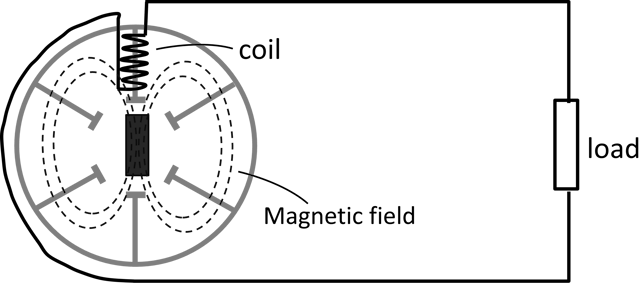
The previous diagram shows how the ac generator (alternator) looks like. The magnetic field of a generator is made to rotate with the help of steam or water turbines.
Why AC varies in magnitude.
NB - to understand this you need to read this article to the very end.
What generaly cause the magnitude (amount) of AC voltage or current to vary with time is the amount of magnetic field cutting across a conductor.
In rotating magnetic field covering stationery coils, at some points they will be no magnetic field cutting across the coils and the value of induced ac voltage is be zero.
At some other points the whole magnetic field will be cutting across the conductor coils and at that point the maximum value of induced ac voltage is obtained.
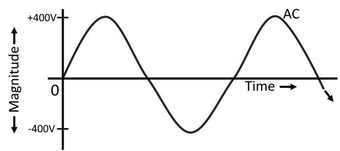
And last at some other points the magnetic field will be partly cutting across the conductor coils which result in voltage induced being between zero and maximum as shown in the following AC sinewave graph. This is why ac is said varies in magnitude.
The following waveform is a sinewave which show the AC values of voltage and current plotted against time
NB - A Waveform is any graph of quantities e.g ac voltage, ac current and more with values which continually vary with time and a Sinewave is an S-shaped graph which the AC voltage and current takes when flowing.
As shown in the following AC sinewave graph, in AC we have:
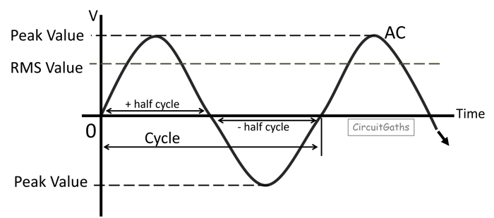
A Cycle
Is a complete rotation of magnetic field - one revolution of magnetic field.
OR
When magnetic field covering the coils of a generator rotate back to its initial position we call that a cycle or one cycle.
The sinewave graph above shows one cycle with a set of complete positive and negative values. The positive half cycle shows electrons flowing in forward direction and the negative half cycle shows a reversal in flow of electrons.
Periodic time
It is the time taken by the magnetic field to complete one cycle. Usually most generator, the magnetic field complete one cycle in milliseconds
Frequency
Frequency is the number of cycles completed in one second, it is measured in hertz (Hz). Most generator are 50 or 60Hz, 50Hz means that, the magnetic field complete 50 cycle in one second.
Frequency is important, electrical gudgets must have the frequency rating which match with that of the supplier of electricity where they're supposed to be used otherwise they will not operate well or stop working.
Peak value
On the AC sine wave, the largest value reached by voltage or currents in each half cycle is called peak value.
Root mean square value (r.m.s value).
This is the effective value which is generally used to represent the AC voltage and current values.
When ever the AC quantity is given it is assumed to be R.M.S value. For example, the domestic mains supply in some countries is 240V and this is assumed to mean "240V rms".
Since AC voltage continually vary in magnitude with time we can't use the instants values in rating of ac appliances or other purposes, they is this r.m.s value we use.
We can better understand r.m.s value in this way:
If we take a DC source and use it to power a certain linear device like a resistor and also take an AC voltage source and use it to power a similar resistor to dc.
If the DC source is adjusted so that the dc load resistor produce the same heat as that of a resistor powered by an AC source.
If the two produce the same heating effect to the load resistors then the voltage and current of dc is equal to that of ac. This is the way the rms value was found.
They are other formulas of calculating the r.m.s value for examle if provided the peak values, the r.m.s value can be calculated by multiplying peak value with square root of two as in the following formula.
R.M.S value = Peak value × square root two.
AC electricity is usually used for generation, transmission, and distribution of electricity because it is easy to generate, easy to change its characteristics which help in reducing loss of energy during transmission and also reducing costs.
DC is mostly used to power electrical gudget which need a steady supply of current such as cellphones, laptops, TVs because they contains electronic components such as transistors which need current which does not vary with time to operate well.
Single and three phase electricity.
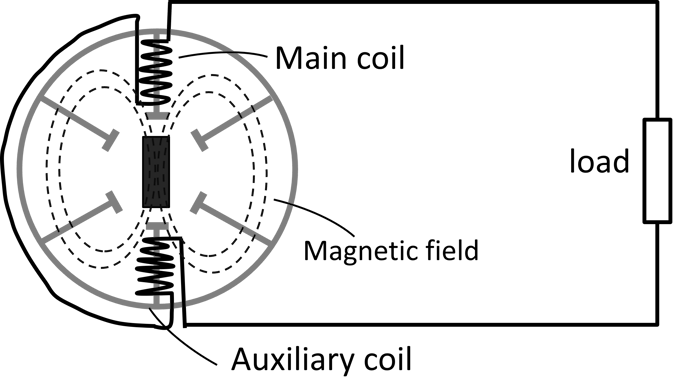
Single phase electricity is when a generator has one independent coil as shown in the diagram below with one live conductor supplying electricity to the single phase loads and a neutral wire returning back to the generator from the loads inorder to complete the circuit.
To increase the length of a conductor inside the magnetic field, the auxiliary coil is added to independent coil as in the following diagram.
To have more phases the generator should have independent coils which are placed at a certain degree from each other, for example in three phase electricity the coils are put 120° from each other as shown in the diagram below.
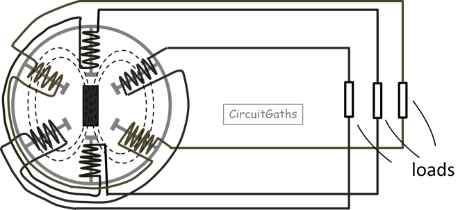
In the previous diagram of three phase electricity we have six conductor, three supplying power to the loads and the other three back to generator from the loads inorder to make the circuit complete.
We can reduce the number of conductors by connecting the generator and three phase load in star or delta connection and the single phase loads will receive power by connecting them to any phase and the neutral wire which emerges from star connection.
Three phase generators and distribution transformers are usually connected in star connection so that a neutral wire is obtained for single phase loads to be connected.
Star Connection
A star connection is when the three live conductors are each connected to a load or coil of a generator and the outlets are joined together as shown in the following diagram.
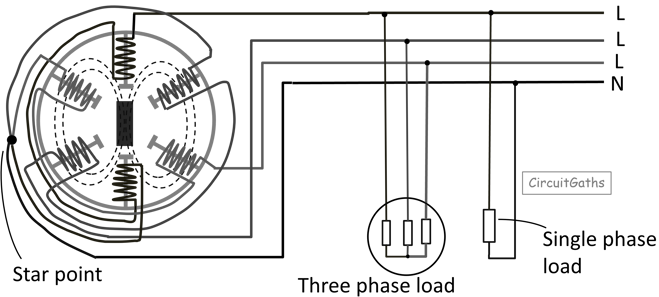
The point of joining the three live conductors is where the neutral wire emerges.
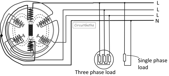
Delta Connection
A delta connection is when the three live conductors are each connected to a load and the outlet from each load is connected to the starting of another load as shown in the following diagram.
If we measure the voltage between the phase and neutral conductor, the voltage we get is called phase voltage. And if between two live conductors the voltage we get is called Line voltage.
Phase voltage is different from line voltage, line voltage is usually higher than phase voltage because in line voltage we are adding two voltages of two phases.
They are various ways of adding phase voltages such as trigonometry phasor addition but more easily using the following formula.
If the phase voltage is provided we can find the line voltage using the formula line voltage is equal to phase voltage multiplied by the square root of three.
Line voltage = phase voltage × square root of three
Some countries uses a phase voltage of 230V and line voltage of 400V.